First week
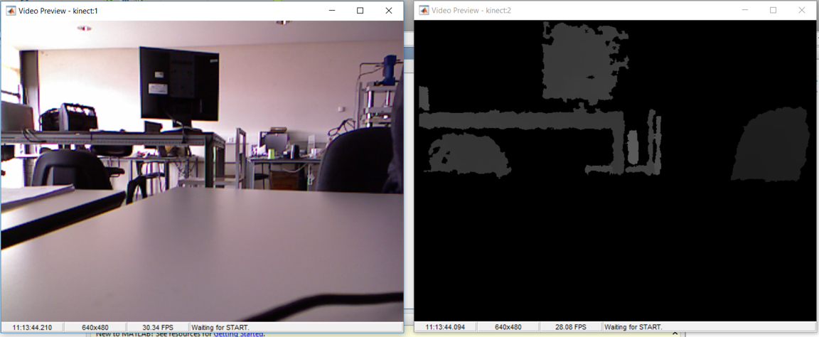
For the beginning some images created using paint were used to simulate the objects that would be expected the future.
The first image was a rectangle with two wholes.
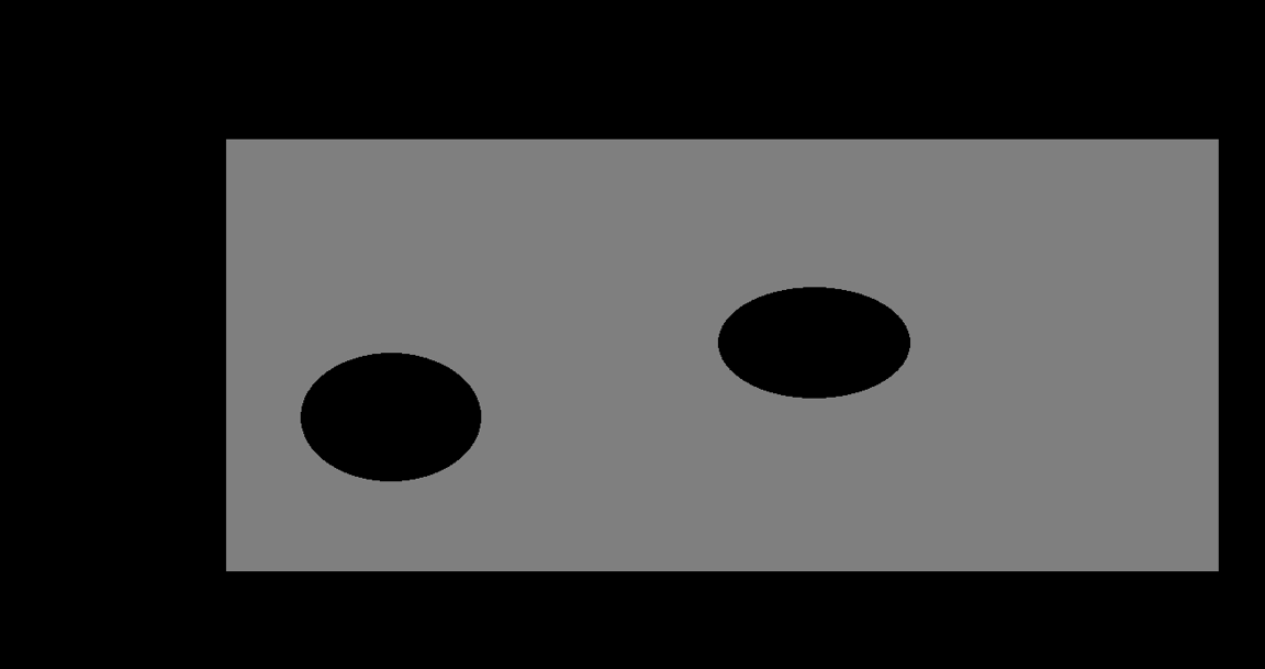 Figure 2 - First image used
This image was converted to gray levels and binarized resulting in a black and white image.
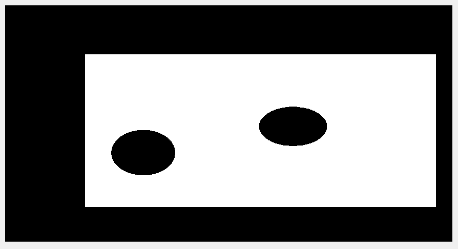 Figure 3 - Binarized image
After getting the image binarized, the object with the biggest area was selected, in this case since there is only one object it is not possible to see the effect. This selection was used to remove possible image nose that could be encounter in an image from the kinect cam.
With only the intended object selected, a mesh was created. First all the pixels from the image were read. Then only the pixels with value one, (pixels that correspond to the location of the object), were selected as valid for the mesh. At last, for cycle was used to select only a few of the valid points of the previous step.
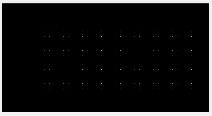 Figure 4 - Mesh created
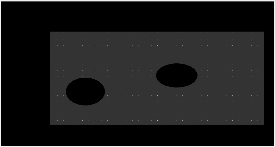 Figure 5 - Representation of the mesh above the surface
Another representation of the mesh were tried using delaunay triangulation but it was hard to control and took more time to compute. The end result is displayed on the next image.
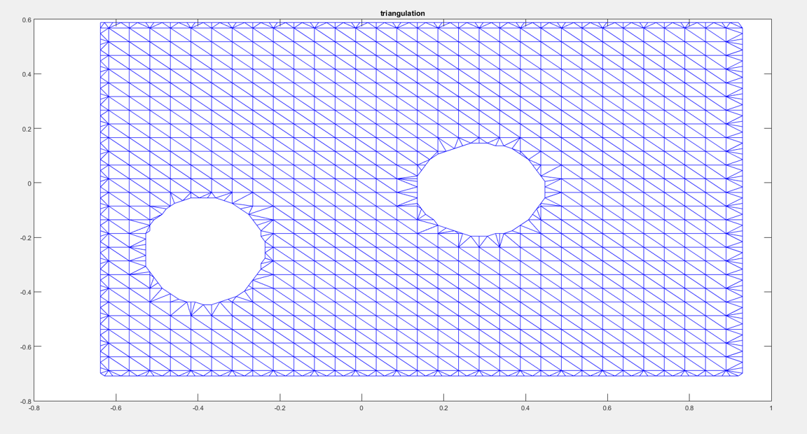
Figure 6 - Mesh using delaunay triangulation
The code used to create this mesh was found at Link
From the images tested, it was reached the conclusion that they needed to be squared and the mesh density would increase or decrease with their dimensions. So the