Tenth week
Also, since the parts were now close to white, the background was now black. The other way around was study but the shadows produced by the parts, usually lead to some confusion by the camera, and the problem was even worst in case of small holes.
The colours tested for the background were red, pink, black and white.
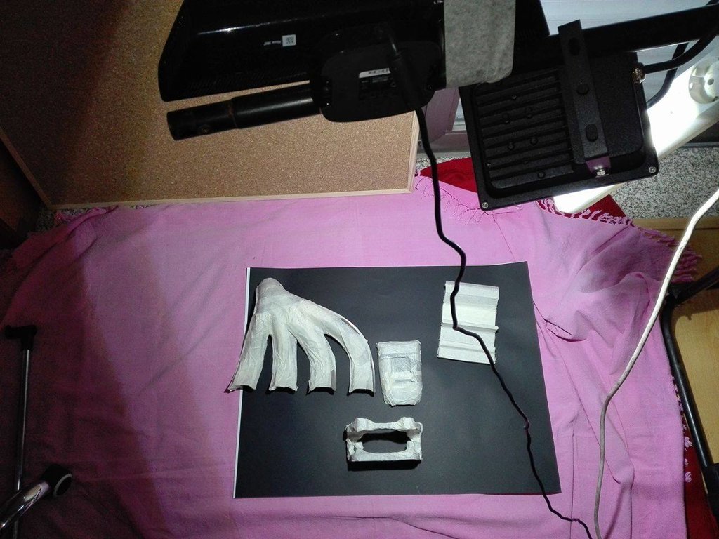 Figure 1 - Environment and object for tests
By testing the objects on figure 1, it was found that in previous tests, camera calibrations between infra-red and rgb sensors were forgotten. This problem is now corrected. To test the functions available to new matlab versions, version R2017a sponsored by Engenius - UA Formula Student was used.
Them, with the calibrations, the two methods used before were refined based on the expected result for the objects on figure 1.
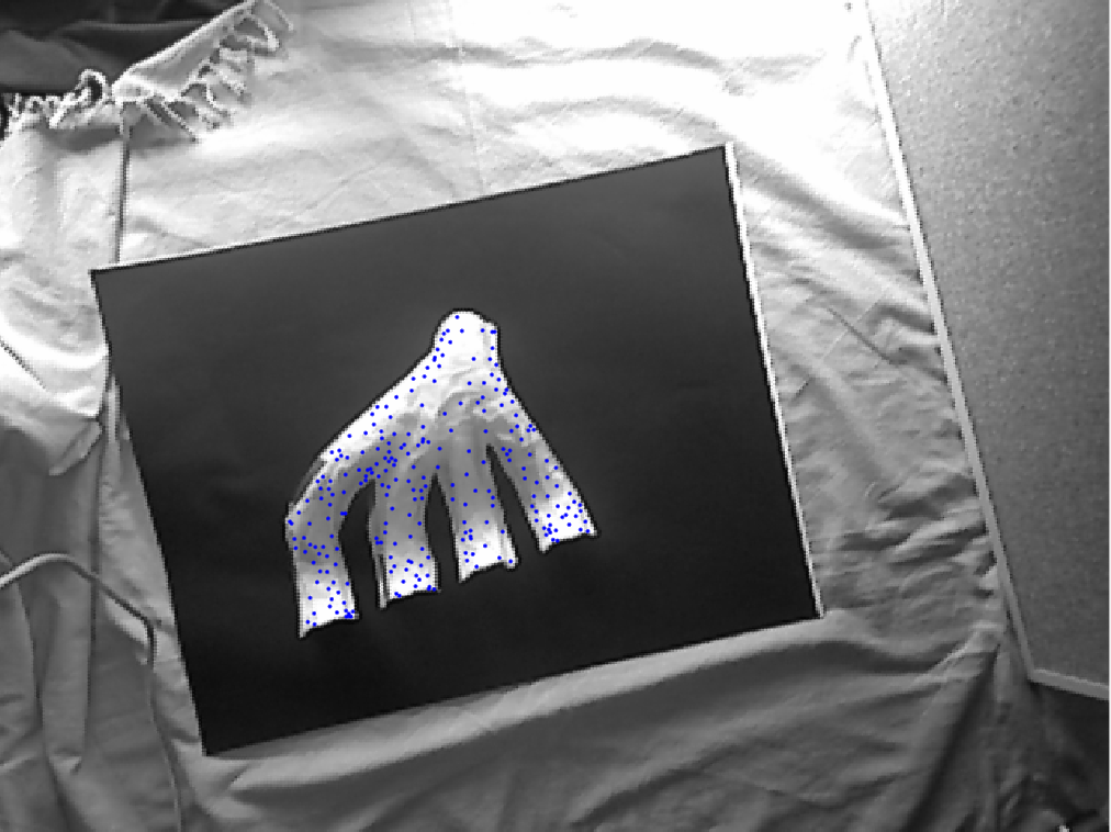 Figure 2 - Result with distance
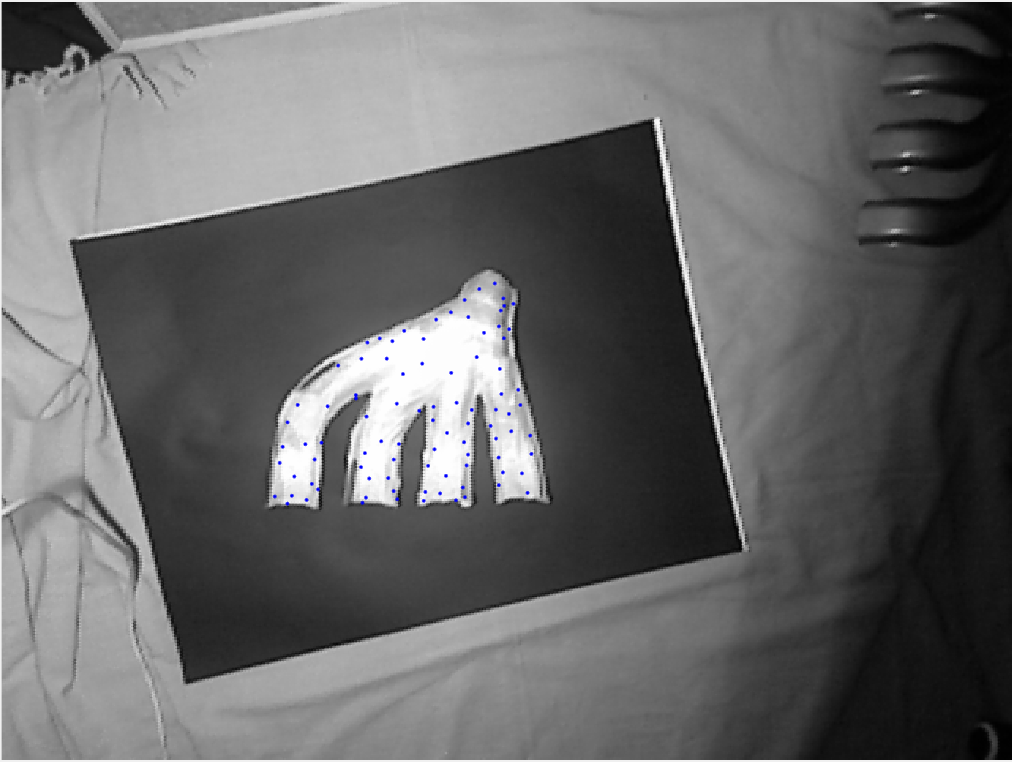
Figure 3 - Result with squares
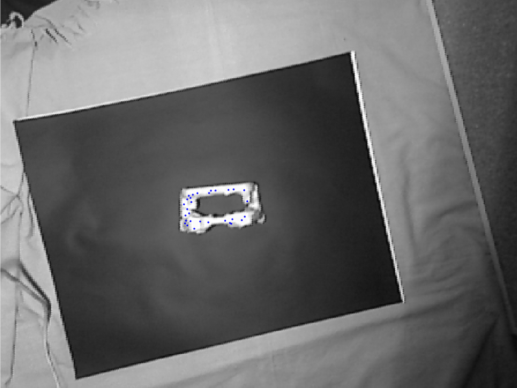 Figure 4 - Result with distance
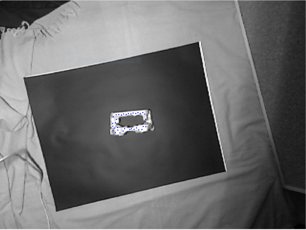
Figure 5 - Result with squares
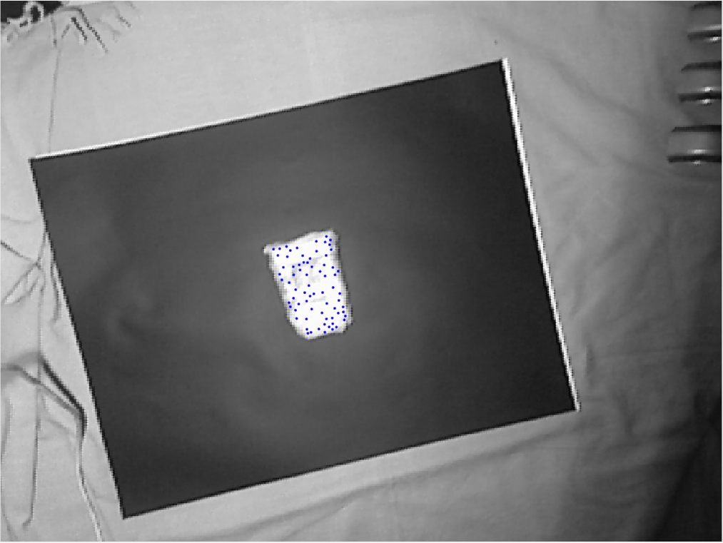
Figure 6 - Result with distance
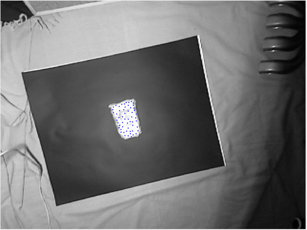
Figure 7 - Result with squares
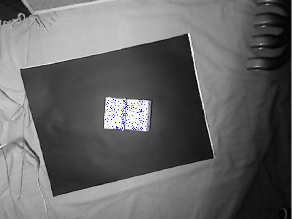
Figure 8 - Result with distance
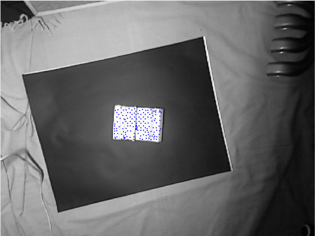
Figure 9 - Result with squares
By studding the digital potentiometer, it was found that it works in steps.
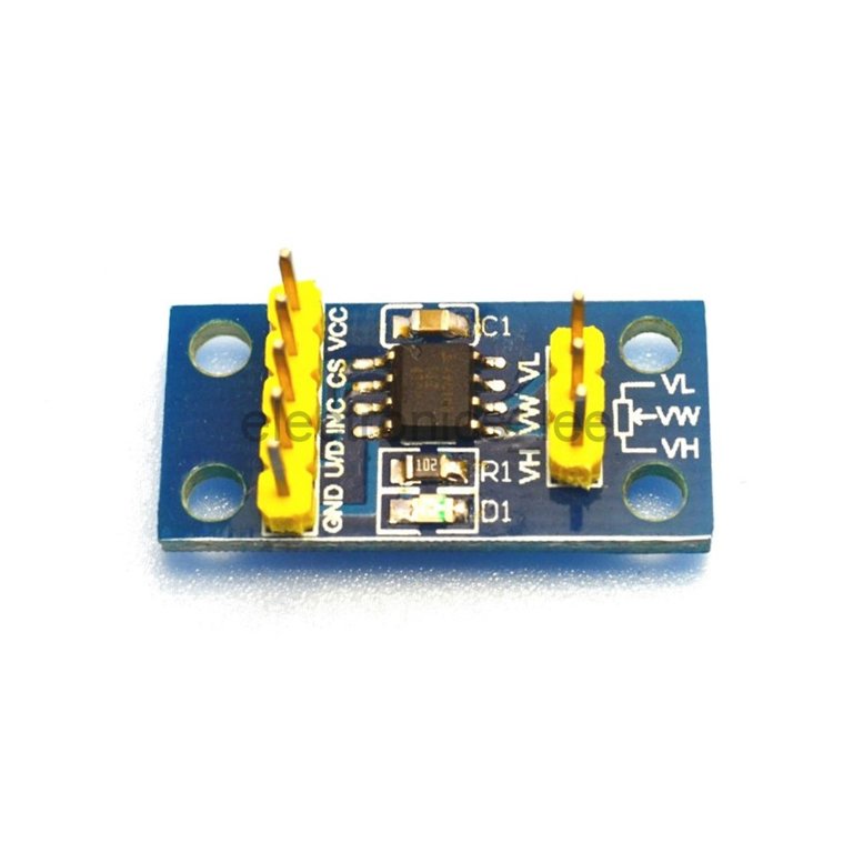 Figure 10 - Digital potentiometer
As it can be seen on the figure above the digital potentiometer has 8 pins. The Vcc and VL are connected to 5V and the GND and VH are connected do ground. The VW is the pin with the intended voltage to control the mirrors on the galvanometer.
To ensure that voltage, pins U/D (up, down), INC (increment) and CS (chip select) need to be controlled.
So, to add one step, CS needs to be low, U/D need to be high and then INC is "pressed" to increment one step by setting it to low.
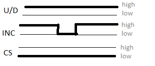 Figure 11 - Add one step to the digital potentiometer
To subtract one step, CS is still low but now U/D needs to be low, then you send low on INC
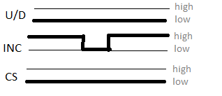
Figure 12 - Subtract one step to the digital potentiometer
To store the wiper value for the next time the device is turned on, U/D and INC both need to be high and then you set CS high.
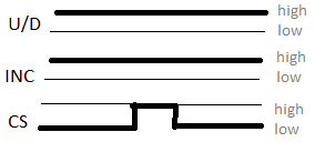 Figure 13 - Save value for the next time the device is turned on
If the CS value is high in any of the previous control steps, nothing happens because the device enters standby low power mode. The information on how the digital potentiometer works was found here youtube link.
The problem with the use of the potentiometer is that it can only get a certain number of values, that are available on the file valores.txt. To get all the values between 0 and 5 V a DAC could be used instead of the digital potentiometer.
Also it seems to be impossible to create a well visible mesh with the galvanometer, tests with the device showed that the trail created by the laser made it seem just one line. If a small delay is set between each step, for 18 points a 4ms delay it too much but 3 ms produces a blurred line.
To finish, the laser pointer used, after approx. 5 meters starts to leave a giant but since the kinect limitations are 4m it is ok.