Twenty sixth week
This way the problems with the address of the DAC's were solved. So the construction of the shield begun. It needs to have the same functions in the same pins as the low pass filter shield so the shields could be replaced without the need to change the arduino code.
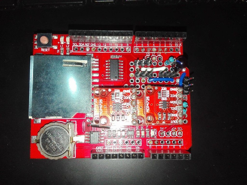
Figure 1 - Top view Shield
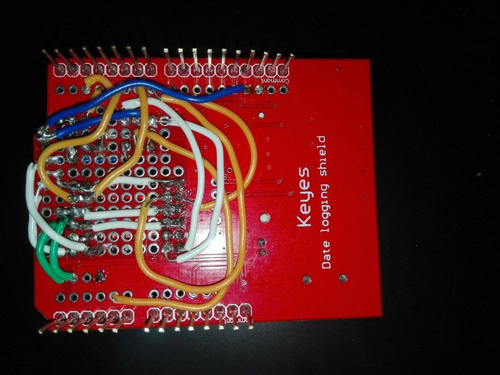
Figure 2 - Underneath view of the shield
The arduino code for the dacs was also built. Leaving only the calibrations to do.
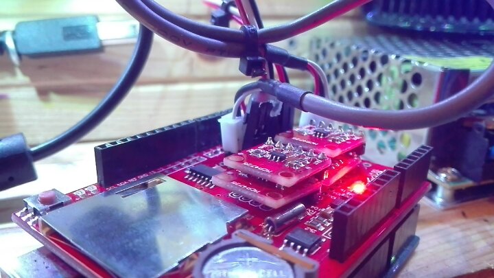
Figure 3 - DAC shield connections.
The purpose of the figure 3 is to show the position of the 2 galvanometer wires are connected for future reference.
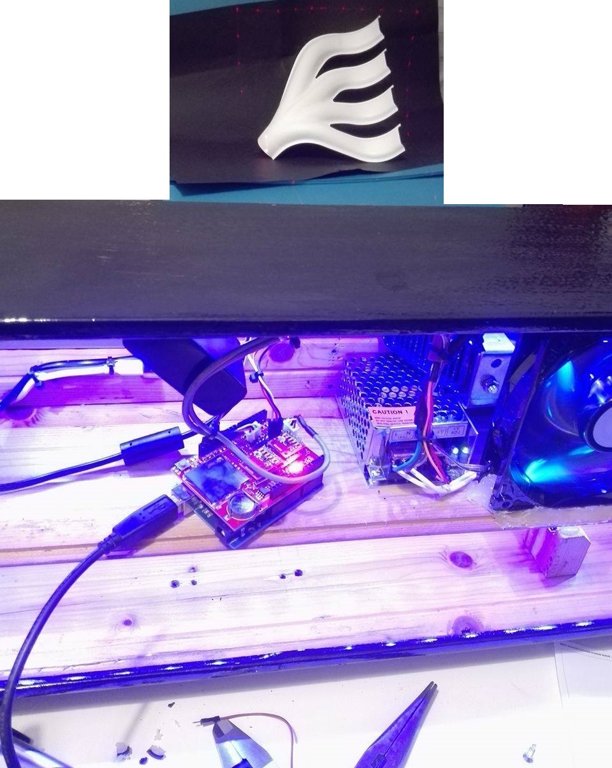
Figure 4 - Using the DAC shield to do a square with the galvanometer limits
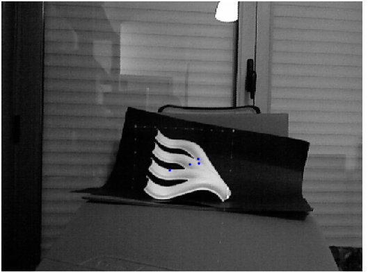
Figure 5 - Mesh points on the computer
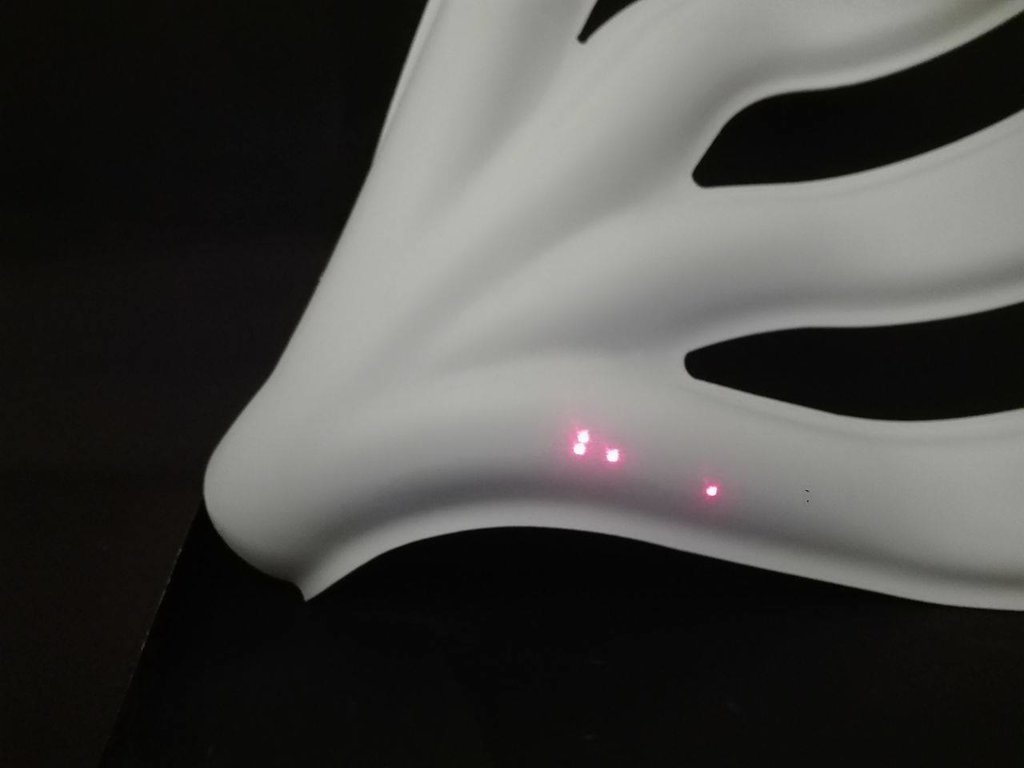
Figure 6 - Result on the object
As said before only the calibrations are missing right now.
As for the green laser pointer, it can use 12v or 5v. Using the 5V from the arduino, the laser has trouble flashing with the same speed as the red pointer. When the laser is connected to the 12v, the bright is super intense, and can cause harm by looking at his reflections. The green laser is class III b. This way the laser that will be used is the red one. This can be changed any time just by removing the red and connecting the green laser, since there is no changes in the code.