Eleventh to Twentieth week
July 3, 2017 at 11:31 pm,
No comments
A first model of the dissertation was written.Tests with the high frequency PWM signal have been done in order to validate the possibility of avoiding an analogue signal.
In the tests with a frequency arround 30kHz PWM, a delay of one millisecond was used for allowing the figure to be visible. With this delay and the high frequency PWM, after just 10 points, adding more would result in the impossibility of they being represented at the same time. Also, and this was the biggest issue, the laser path would have some inconsistencies, since it had the same effect as if it was being turned on and off. The first attempt to solve this issue, was a low pass filter, but the effect was the same as high frequency PWM alone.
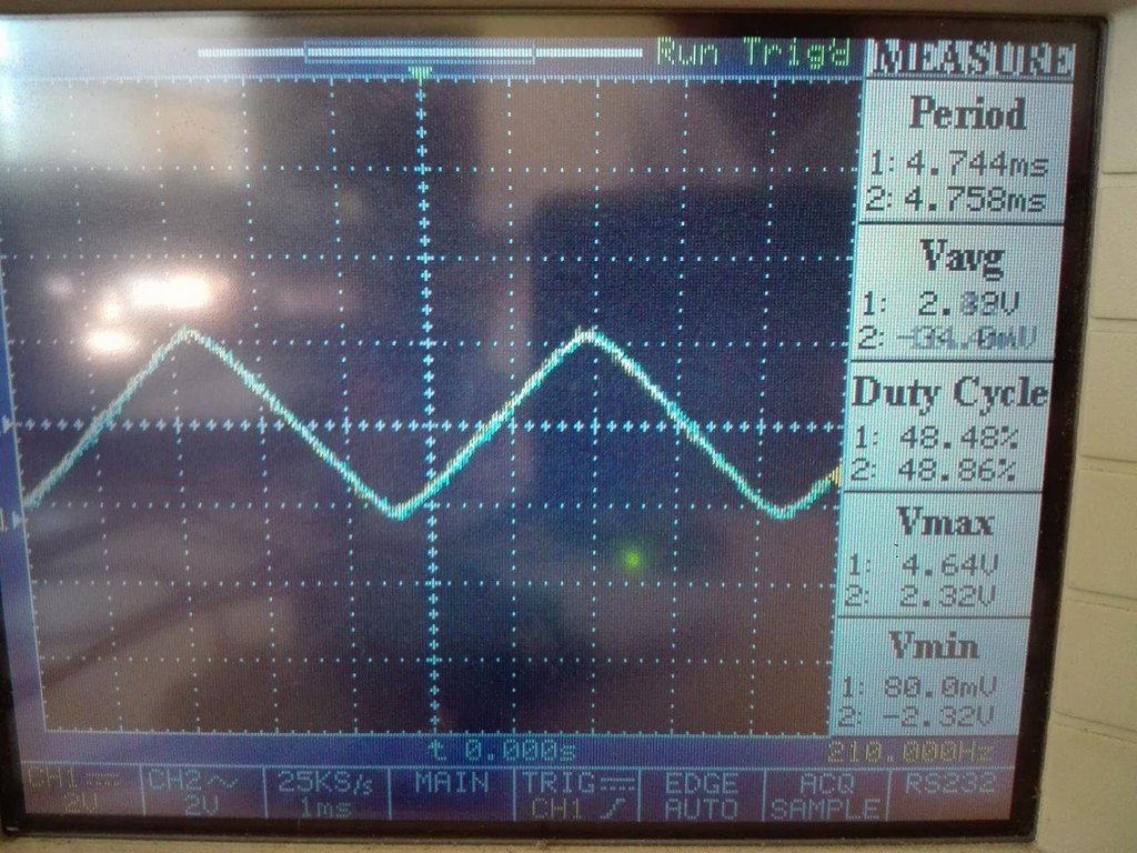
Figure 1- Result with the low pass filter, analogue write loop cycle from 0 to 255 and 255 to 0.
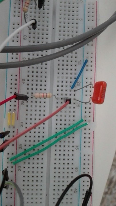 Figure 2 - Low pass filter used
The filter was used with a pwm frequency of 200kHz.
Manual work:
- Laser pointer was glued to the base.
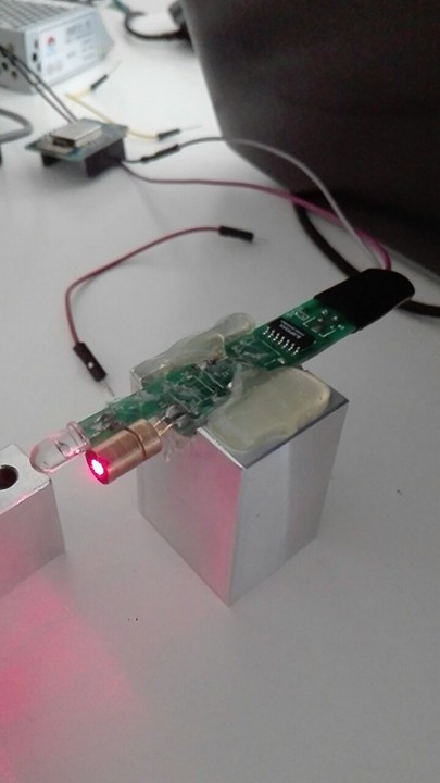 Figure 3 - Glued laser pointer
- Galvanometer was screwed to the base.
Since the laser pointer on figure 3 stopped running, another one was bought. All the problems with the galvanometer part were solved with this exchange.
Then to test the laser a figure was drawed.
 Figure 4 - Pikachu figure
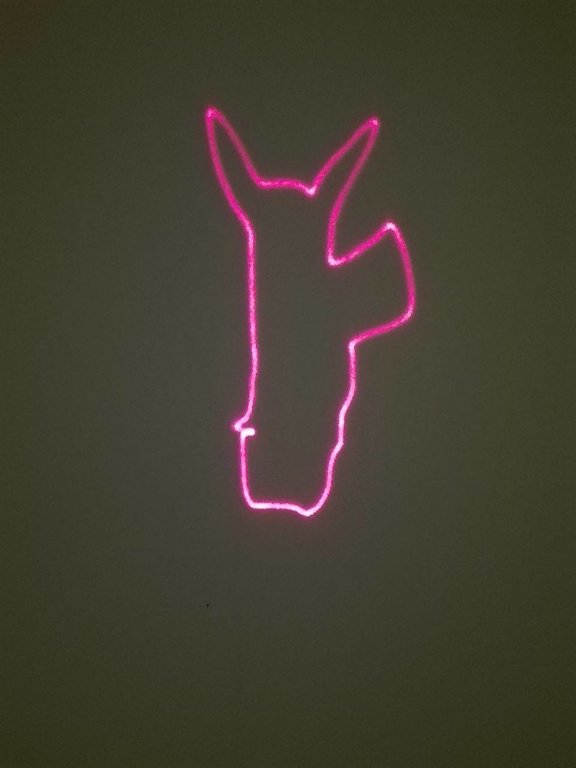
Figure 5 - Pikachu contours with the galvanometer
There is a problem with the leg of the pikachu but its possible that this problem was created when the coordinates of the leg were being copied to the arduino, since the rest of the shadow is ok. The image looks different from the figure 4 because of the scale.