Twenty fourth to Twenty fifth weeks
- Time to write 40 points (square) without delays - 1812 microseconds;
- Max number of points of the galvanometer - 20 000 points per second;
- Points to get 20 frames - 1000 points (20 000/20) ;
- To represent something 20 times per second means 1000 points in 50 ms;
- Delay according to the number of points - 1000 points in 50 ms, means 1 point with a delay of 50 microseconds.
Tests with the arduino showed that the galvanometer can't handle that speed, instead the pause was 140 microseconds. The figure used to test it was a square with 10 points in each side. Then, by turning the laser on after the 140 microseconds delay, it was observed that it was on before the galvanometer reached it's destination. So in order to turn on the laser when the location of the mirrors was the intended point, the necessary delay was 700 microseconds. Then, for the laser to be seen it would need a delay of 50 microseconds. The final delay is 750 microseconds. with means that only 66 points will be possible at 20fps.
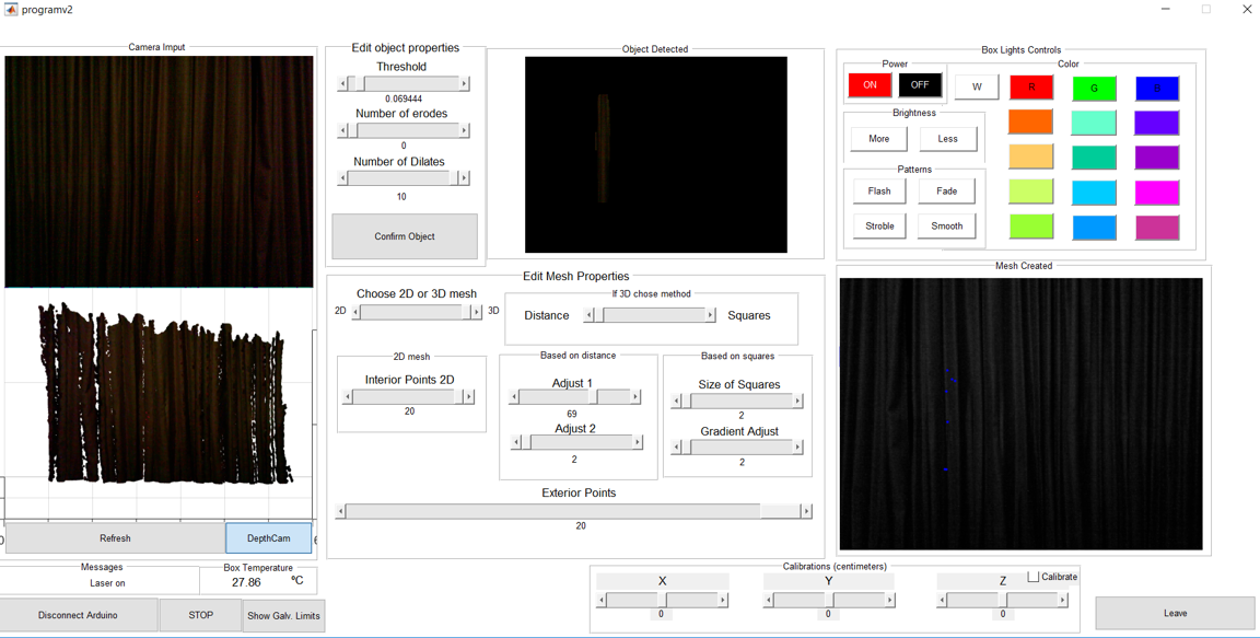 Figure 1 - New app ( the calibrations panel still needs work)
The new app allows to:
- Control the box lights;
- See the box temperature;
- View the point cloud in real time from the kinect; ( it's possible to hide it and see the depth cam image instead.)
- Show the galvanometer limits to show the user, where to put the part.
To change the colour of the box lights, infrared communication between the arduino and the lights (bought with the receiver) was established. 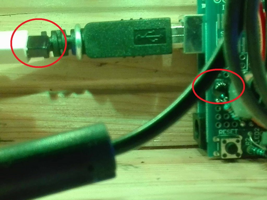
Figure 2- IR sensors
To read the temperature, a temperature sensor was installed on the top of the second shelf. Since the drivers of the galvanometer, when "online", heated up to a reasonable temperature, a fan was installed. The fan speed is always maximum since its connected directly to the 12V power source. The decision to keep it that way was the lack of time.
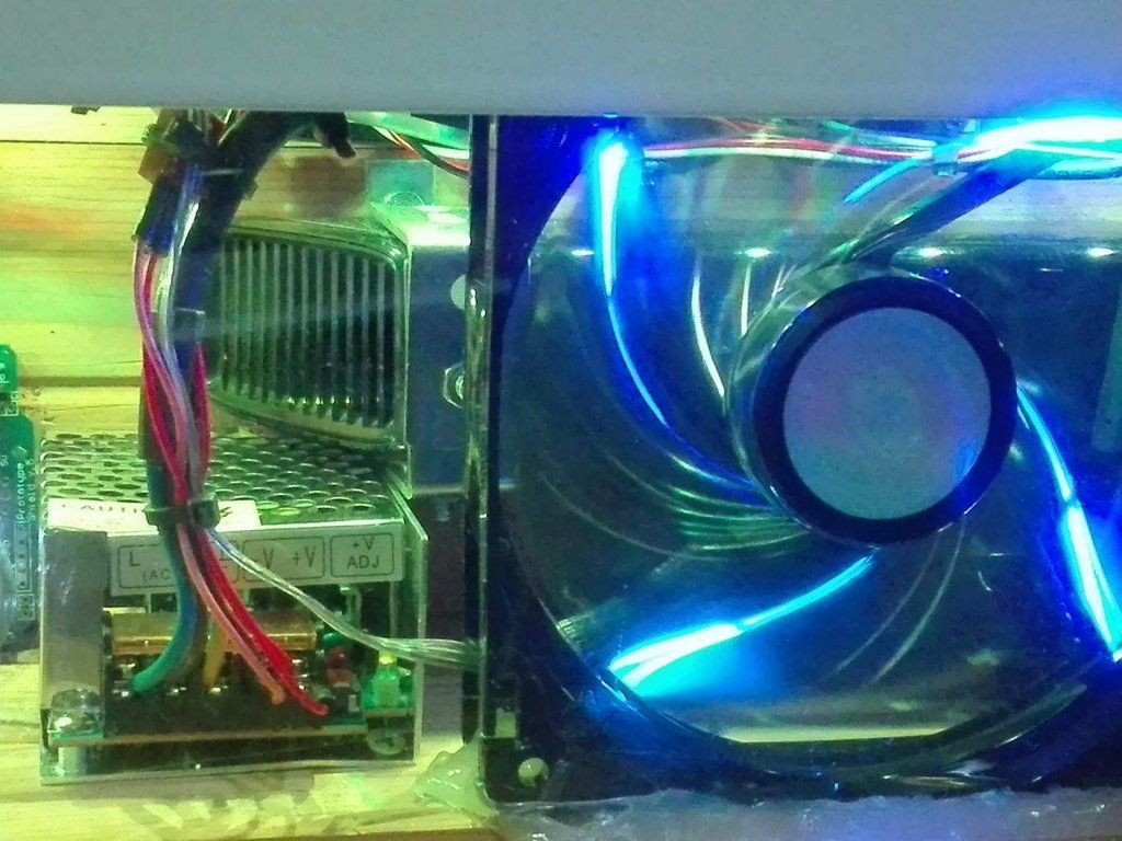 Figure 3 - Fan and 12V power source
To work the the serial port, more code on the matlab and arduino was developed.
One timer was created on the arduino to send the temperature every 2 seconds and another two were created on the matlab for the app, one to update the point cloud every 250 milliseconds and another to look for COM ports available.
The code for the arduino to recieve the data of the points was rewritten. The readuntilstring() function, when used to read large strings fails. So an alternative function used to read the string char by char and build the string. Then getValue() was used, which was found on link, separates the string in smaller strings by the char ";", which was the same used before. Since the entire string was saved, no need to create a matrix to save it, so that part was deleted and instead of readding a matrix, the string will be read.
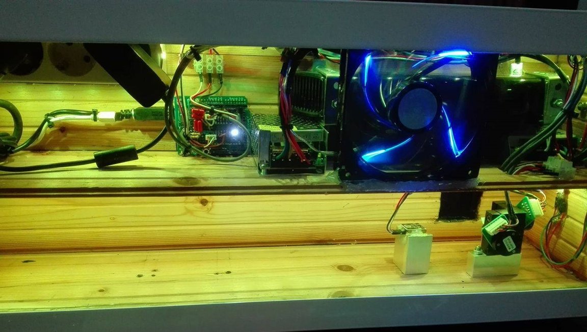
Figure 4- Box aspect inside at this date.
To avoid having 3 wires laying around, a solution with a usb hub and a usb extension cable was studied but the kinect somehow detects when it's not connected directly to the computer, so that solution was left behind.
Also, to try to only use one low-pass-filter for each mirror, a solution with a logical gate was tested, but it was found that the logical gate only works at 100% with a digital signal. So, two more low pass filters were built into the arduino shield, since the logical gate was already welded. This way, 2 pwm signal are sent, and 4 digital signals control each one of the gates. The pwm signal is sent to both pins on each mirror (up and down), and, other arduino pin controls if it is on or off.
Results.
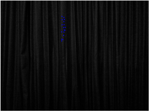
Figure 5 - Computer plot ( intended points)
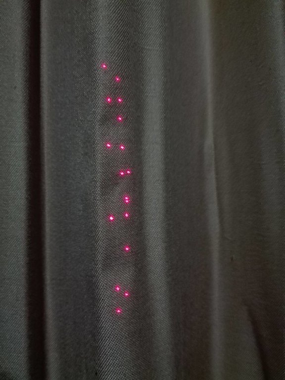
Figure 6 - Real world result
Since the old platform to hold the laser was made for the first points, its dimensions were wrong, so a new platform was built in wood for the both laser pointers, the 5mw and the 80 mw lasers.
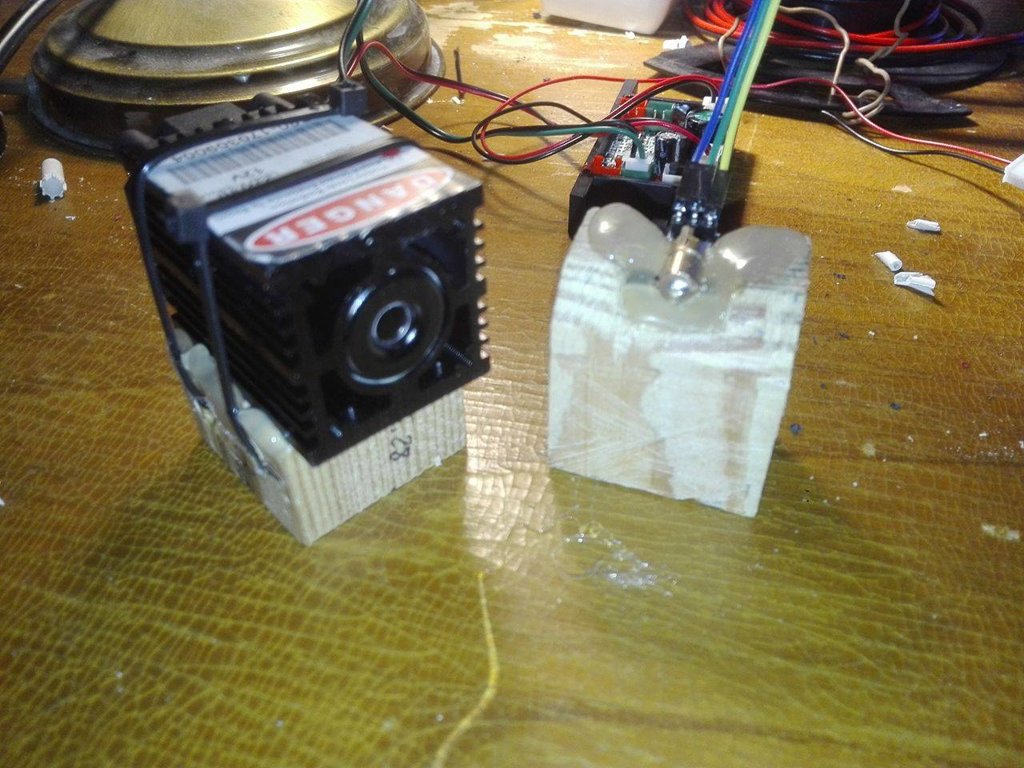 Figure 7 - Laser platforms
Also, for the vision component, a light was installed on the front of the box. Since there was no relay available at the time, a button was also installed.
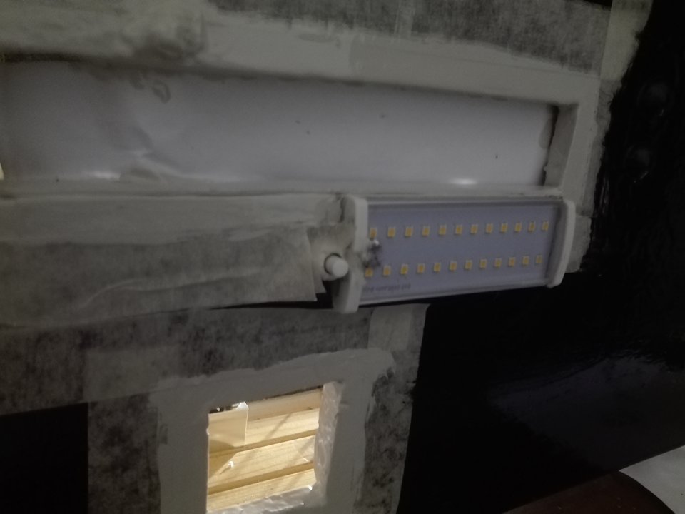
Figure 8- LED light and button
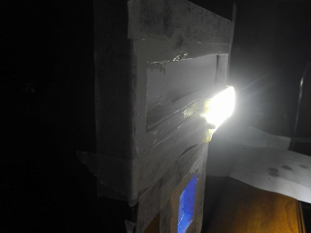
Figure 9 - LED light on
The light is positioned right under the rgb cam of the kinect.
DAC experiments
The dac that will be used on the work are the MCP4725. This device communicates via I2C. This kind of communication is made using the address of each device. Since the DAC's have the same address it's impossible to send commands to just one. So, ways to change the address have been searched. A solution was found on link which said "To change the address of your other device, simply de-solder the jumper and add a blob of solder to the middle pad and the Vcc pad."
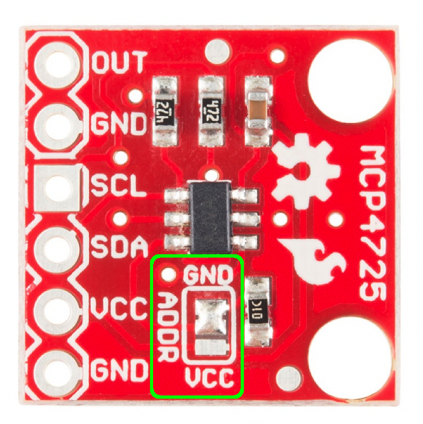
This way the addresses 0x62 and 0x63 were possible. Since only 2 DAC's were necessary at a time, the vcc pin was set to 0v on 2 DAC's and 5 on the other 2. This was supposed to allow to operate one DAC at a time but instead the system froze.